Introduction to Work in Chemical Laboratory
(Redirected from Introduction to work in chemical laboratory)

Measuring Volumes[edit | edit source]
Volumetric Vessels and other Tools in the Chemical Laboratory[edit | edit source]
Various laboratory vessels and devices are used for preparation of solutions and manipulation with liquids. They differ in the intended use and accuracy. Precise volumes must always be measured at constant temperature because, due to thermal expansion, changes in temperature are followed by changes in volume. For example water at 10 °C has much smaller volume than at 80 °C.
Volumetric vessels are usually calibrated for 20 °C (25 °C in the USA). Calibration temperature is written at every volumetric vessel. Substantial error may result e.g. from change in temperature during dilution of an acid. A lot of heat is released during dilution and temperature increases. When the volume of acid is measured immediately, the real volume after cooling-down will be smaller. The requirement for constant temperature must therefore be observed.
| Device | Usual range of volumes | Accuracy |
|---|---|---|
| Erlenmayer flask, beaker | 5–5000 mL | * |
| Volumetric flask | 5–2000 mL | high |
| Volumetric cylinder | 5–2000 mL | medium |
| Burette | 1–100 mL | high |
| Pasteur pipette | 1–5 mL | low |
| Glass pipette | 1–100 mL | high |
| Pipetor | 5–5000 μL | high |
| Automatic dispenser | 0.1–100 mL | medium |
| Microsyringe | 0.5–1000 μL | high |
| piston dispenser | 1–500 ml | medium |
* not suitable for measuring volumes, only approximate volume indicated
Beakers[edit | edit source]

Beakers are used for approximate determination of the volume of liquids and thus are not necessarily classified as measuring tools. They are used especially for dissolving compounds, diluting liquids, heating and other operations. Beakers are unique for there 'beak' that is used to pour liquids. Because of low accuracy, they are frequently not classified as volumetric devices.
Volumetric Flasks and Cylinders[edit | edit source]

Volumetric cylinders and volumetric flasks are used to measure volume of liquids contained in them. They are calibrated for volume included in them - this is indicated by the marking "IN". The liquid has accurate volume when it reaches the corresponding marking on the scale. Volume is usually indicated in mL. During measurement of the volume the vessel must be placed on an even, horizontal support. The required volume is measured when the lower edge of meniscus of the liquid just touches the marking on the vessel. Cylinders are less accurate, volumetric flasks are used for preparation of solutions of exact concentration. Cylinders are used solely for measuring volume, they are not employed for dissolution, dilution or mixing.
Burettes, Pipettes, Dispensers and Syringes[edit | edit source]
Burettes, pipettes, dispensers and syringes measure volume of a liquid delivered to another vessel.
Pipettes and burettes are usually calibrated for outpouring. It is indicated by letters "EX" (from exclude). The exact volume is measured when the liquid is kept to flow out from a certain marking on the scale. Some liquid may remain in a pipette after outpouring; it should never ever ever be blown out, its volume was taken ito account during calibration.
- Burettes.

Burettes are used for titrations or whenever the same liquid is repetitively measured. Burette is a glass or plastic tube with calibrated scale closed with a stopcock. Burette is attached to a stand in a vertical position. With a closed vent, it is filled with the measured liquid. Some liquid is then outpoured so that the meniscus touches marking of the scale. Now, burette is ready for titration. The liquid is outpoured with the stopcock and the volume is read on the scale. The most important moment is reading the volume; with burette, the volume is always read twice: first to read the starting position of the meniscus and the second time to read the end position. As the difference in volume is calculated, it is not important how exactly the volume is read, it must however be read in the same way every time.
- Automatic burettes are employed in routine laboratories.
- Glass pipettes.

- Today, glass pipettes are rarely used in contemporary routine laboratories; glass pipettes were replaced by semiautomatic dispensers. The volume of glass pipettes may vary from 1 to 100 mL. Glass pipettes can be non-scaled for measuring of a certain volume or scaled with grades by 1 mL and tenth of milliliter. Numbering of the scale can go from the tip up or in the opposite direction.
- For security reasons, a liquid should never be aspired by mouth. Various adapters and pistons are used instead.

- When aspiring the solution, the pipette should never touch the bottom of the vessel. Before measuring a sample the pipette should be filled with the solution first and the liquid is then thrown away. Then the exact volume is measured and delivered for further processing. The measured solution must never get into the adapter.

- Pipettors (automatic pipettes, micropipettes, microdispensers).
- Another possibility of measuring small volumes is use of micropipettors. They are always calibrated for outpouring.
- Microsyringes.
- Microsyringes serve for dispensing small volumes (0.1–1000 μL) of liquids. They consist of a needle attached to a scaled glass cylinder with a piston. Different types vary in the diameter of needles and pistons.

- Piston dispensers.

- Piston dispensers consist of a piston with a scale attached to a flask. They are intended for repetitive dispensing of the same volume from the stock container. Dispensers designated for measuring aggressive liquids (e.g. strong acids) are made of borosilicate glass; plastic parts that are in contact with measured liquid are made of PTFE, the other parts of PE or PP. Electronic control modules may automate dispensing in contemporary dispensers.
Pipettors[edit | edit source]

According to the way of operation, manual and electronic pipettors can be distinguished. In manual pipettors, the piston is moved by a thumb using an operation knob. Accuracy and precision of pipetting depend on expertise of the operator. In case of electronic pipettors, the piston is moved by a small electric motor. Different speeds of aspiring and expressing of the liquid can be selected according to properties of the pipetted solution.
According to the principle of operation, pipettors can be divided into two big groups:
- „Air displacement“ pipettors
- Principle of so called air cushion is employed in this type of pipettes. A certain volume of air is between the piston and measured liquid. The volume of solution and of the air aspired or expressed with the piston may differ. It depends on density and viscosity of the liquid, wettability of the surface of the tip with pipetted liquid, temperature, athmospheric pressure and other influences. Thus, every pipettor must be calibrated on a regular base.
- Air displacement pipettors can be designed as a single channel (for pipetting of a single volume at a time) or as a multi channel (most frequently with eight or twelve channels). Multi-channel pipettors are intended for simultaneous pipetting of the same volume of liquid to several wells of a microtitration plate. Every channel has its own piston; therefore, it is not necessary to use all 8 or 12 channels (i.e. less tips can be attached to the pipette).
- Micropipettors are constructed for one fixed volume or it is possible to set the volume. Volumes can be set discretely (changing of plug-in modules) or continuously in a certain range (e.g. 10–100 μL) using an adjustable screw or knob. At the lower end of a micropipette there is a removable tip. At the other end, there is the knob operating the piston inserted into the cylinder of the pipettor.
- „Positive displacement“ pipettors
- Liquid is aspired into the tip without any air cushion – the piston is in contact with measured liquid. The liquid is then delivered at once or in several steps (in case of so called "steppers"). This type of pipettors is suitable for very viscous or voilatile liquids and for repetitive pipetting.
Operating a Pipettor[edit | edit source]

Forward pipetting This is the most frequently used technique. In forward pipetting, an exactly set volume of liquid is aspired to the tip and then it is delivered to a new vessel. This technique is recommended for pipetting of diluted aqueous solutions, bufers, diluted acids and bases.

Procedure:
- Attach a tip to the pipettor. Press the button to the first stop (it is necessary to overcome a slight resistance).
- Dip the tip approx. 2-3 mm under the solution level. Release the button slowly; the solution is aspired to the tip.
- Slow aspiration prevents tubulences that would lead to formation of aerosol and bubbles of gas dissolved in the solution. The optimal speed depends on properties of the liquid (density, tension of vapors and viscosity).

- Pay attention not to aspire air bubbles (e.g. when the piston is released to quickly or if the tip is not attached properly).

- Higher accuracy can be reached if the thumb is completely removed from the button after it has reached the released position.
- Slow aspiration prevents tubulences that would lead to formation of aerosol and bubbles of gas dissolved in the solution. The optimal speed depends on properties of the liquid (density, tension of vapors and viscosity).
- Take the tip off the liquid slowly. Fast removal may lead to loss of a portion of the content. Before removing the tip, wait several seconds especially when working with larger volumes (500–5000 μL).
- When necessary, wipe droplets from the external surface of the tip with tissue cloth. Never touch the orifice of the tip, the cloth would absorb a portion of the transfered volume.
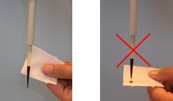
- During delivery of the liquid, the tip should touch a wall of the vessel at an angle (10–45º). It should be just above the level of any liquid that already is in the vessel. Push the button to the first stop. Wait for approx. 1 second and push the button quickly to the second stop (a stronger resistance can be felt). No droplets should remain in the tip and no liquid should be splattered on the walls.

- Hold the button in the second position and remove the tip, still touching the wall of the vessel. Now you can release the button.


Forward pipetting brings a small error in the delivered volume as a thin film of pipetted solution remains on the inner walls of the tip. In other words, according to the described procedure a slightly smaller volume than required is delivered. This error depends on properties of measured liquid and of the tip. The error can be avoided if the inner wall of the tip is pre-rinsed with the measured liquid. Practically, liquid is first aspired to the tip. Then it is not delivered to a new vessel but returned back to the stock vessel. Now, a very thin film of pipetted liquid covers the inner wall of the tip (it is usually invisible). Pipetting according to instructions given above follows (without changing the tip). As the volume of liquid remaining in the tip is practically constant, exactly the set volume is measured.
Reverse technique
In reverse technique, a larger volume of solution is aspired to the tip. Then, an exaxt volume is delivered (and some liquid remains in the tip). This technique is suitable for very viscous or volatile liquids, biologic fluids, foaming solutions and for measuring very small volumes.

Procedure:
- Push the button to the second stop.
- Dip the tip 2–5 mm bellow the level of the solution. Slowly aspire the solution to the tip.
- Remove the tip slowly from the solution. If necessary, wipe droplets from the external surface of the tip.
- Deliver the liquid to a new vessel, pushing the button to the first stop only. The tip should touch the wall of the vessel similarly to the forward technique.
- Hold the button in the first position and remove the tip from the vessel.
- The liquid remaining in the tip can be returned to the stock vessel or thrown away.
Repetitive pipetting

This technique is used when the same volume of the same liquid is to be measured to several test-tubes or to many wells of a microtitration plate. It is similar to reverse pipetting where steps 2 to 4 are repeated several times.
Pipetting of heterogenous samples This technique is suitable for heterogenous samples like whole blood. Pre-rinsing of the tip before pipetting is not easy in this case.

Procedure:
- Push the button to the first stop and dip the tip approx. 2–5 mm beneth the solution level.
- Slowly release the button. The sample is aspired to the tip.
- Remove slowly the tip from the solution and wipe droplets on the outer wall of the tip.
- Dip the tip into the target solution.
- Push the button to the first stop and then slowly release back. The solution will be aspired. Do not remove the tip from the solution and repeat this step until the inner wall of the tip is clean.
- Touching the wall of the vessel, place the tip above the level of the solution and push the button to the second stop.
- Hold the button at the second stop and remove the tip from the vessel.
Filtration[edit | edit source]

Filtration is employed to separate a dispersion according to the size of particles. The filtered mixture is applied on a filter made of a suitable porous substance. Particles smaller than the pores can cross the filter and get into the filtrate while larger particles are trapped on the surface of the filter.
Filter[edit | edit source]
Filters are made of various materials. Filtering papers belong to the most traditional ones – these are special unsized papers of a suitable porosity. Gauze, cotton wool, glass wool and other materials can be used to filter out rough particles. On the other hand, speciality mambranes made for example of celulose acetate, PVDF, nylon or other materials are used for separation of smaller particles.
Arrangement of Filtration[edit | edit source]
Filtering solution through filters with very small pores is time consuming. The process is faster if the pressure of filtered liquid is incresed (high-pressure filtration) or the filtrate is aspirated (vacuum filtration).
The most simple example of high-pressure filtration is use of syringe filters. The filtered mixture is aspirated to a syringe. Encapsulated membrane filter is attached to it. Overpressure is reached with the piston of the syringe.
Syringe filters are used e.g. for sterilising solutions like eye drops in pharmacies.
A similar principle is employed in centrifugation filters. In this case, the filtration unit resembles a test-tube or micro test-tube. Vhen the compartment for sample is filled with the filtered mixture, the whole unit is placed into a centrifuge. The centrifugation force speeds up the process of filtration.
Vacuum filtration is, on the other hand, based on aspirating the filtrate. In the classical arrangement, the filtration membrane os placed on the Büchner funnel that is attached to a vacuum flask. Disposable filtration units for vacuum filtration made of a suitable plast are available today as well.

|

|

|
| Syringe filters (from [1]) | Centrifugation filter (from [2]) | Vacuum filtration (from [3]) |
Filtering through a Paper Filter[edit | edit source]

- A circle of a filter paper is folded to quarters. Then it is unfolded so that it forms a cup.
- The cup is placed into a funnel. Frequently, it should be moistened (usually with distilled water).
- During filtration, the stem of the funnel should touch a wall of the collecting container. The filtered mixture is poured onto the triple layer of the filter paper.
- The filtered mixture must be added slowly. It must never reach the top of the filtration paper or even overflow it.
This article achieved ecxatly what I wanted it to achieve.
Instructions and Protocol for the Laboratory Lesson (2010/2011)[edit | edit source]
- Instructions for the practical lesson Introduction to work in laboratory
- Protocol for practical lesson Introduction to work in laboratory
Links[edit | edit source]
Related articles[edit | edit source]
References[edit | edit source]
- ↑ Labicom. Filtrace [online]. [cit. 2009-10-26]. <http://www.labicom.cz/default.aspx?section=142>.
- ↑ National Scientific. Centrifugal Filters [online]. [cit. 2009-10-26]. <http://www.nationalscientific.com>.
- ↑ Dartmouth College. ChemLab. Vacuum Filtration [online]. [cit. 2009-10-26]. <http://www.dartmouth.edu/~chemlab/techniques/vfiltration.html>.