Forum:Seminar papers/Biophysics/2. LF/2018-2019/Group 7/Bessisso/Varys
< Forum:Seminar papers | Biophysics | 2. LF | 2018-2019 | Group 7
Brainstem Evoked Response Audiometry (BERA)
- BERA (syn. BAEP, ABR) is an objective examination of acoustic evoked potentials (AEPs).
THEORETICAL Introduction[edit | edit source]
- Evoked Potentials (EP) are bioelectric impulses brought about by specific stimuli from the outside world, which spread through specific neural pathways. EP are categorized into several categories based on the type of stimulus and the specific neural pathway as follows:
- VEP (Visual EP)
- AEP (Acoustic EP)
- SEP (Somatosensoric EP)
- MEP (Motoric EP)
Physiology of hearing
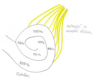
- Sound is a longitudinal mechanical wave with the range of frequencies 16 – 20 000 Hz. The brain isn’t capable of directly processing this mechanical energy, therefore it is necessary to transform it into a bioelectric signal. Hair cells, in the organ of Corti in the cochlea of the ear, are responsible for this transformation. These hair cells react to specific frequencies of sound waves (hair cells in the basal turn of the cochlea react to higher frequency; hair cells in the apical turn react to lower frequency). Under the influence of the sound waves, the stereocilia of hair cells bend and the Calcium channels open, which triggers the depolarisation of the hair cell membrane and the subsequent release of neurotransmitters in the basal end of the cell against the dendrite neuron of the auditory nerve. Irritation of this nerve creates a bioelectric signal, which spreads down the auditory neural pathway. A signal created in the cells of the basal turn of the cochlea is received by the brain as a high frequency tone, a signal created in the cells of the apical turn is received as a lower frequency tone.
Auditory Neural pathway
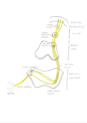
- Bioelectric signals spread through the auditory neural pathway. The anatomical structure of the auditory path is shown because the results from the examination of hearing potentials is a curve showing the dependence of the time of start of the electric impulse with sound frequency. Each time of start of the electric impulse is specific for a given anatomical structure of this pathway.
- Cochlea
- Nervus Cochlearis
- Nucleus Cochlearis (Ventralis et dorsalis)
- Nucleus olivaris superior
- Lemniscus lateralis
- Colliculus inferior
- Corpus geniculatum mediale
- Radiation Acustica
- Cortex auditoria
Acoustic Evoked Potentials (AEP)
- AEP is an action potential triggered by an acoustic stimulus, which spreads through the auditory neural pathway. This bioelectric signal can be measured as an electric potential using an electrode on the surface of the skull (or throughout the neural pathway) as in an EEG exam.
The result of the AEP exam is a curve which shows dependence of electric potential (detected in the electrodes) with time (measured from the moment that the acoustic stimulus is sent). Because it takes some time for the bioelectric signal to pass through the auditory pathway, it is possible to identify the number of separate waves on the curve. Each wave is considered an electric “response” to each specific part of the auditory pathway.
Using the record of electric potentials, it is possible to measure the electric answers to each specific part of the acoustic neural pathway. The time between sending out the acoustic stimulus and the record of the specific wave is said to be the latency window of the wave.
Based on the amount of time between the sending of the stimulus and the record of the bioelectric signal (period of time called the latency window), we divide the examination of AEP into the following:
- 1. Early latency potentials
- Electrocochleography – latency window 0-4 ms
- Examination BERA (BAEP, ABR) – latency window 2-10 ms
- 2. Medium latency potentials (examination MERA) – latency window 15-50 ms
- 3. Late latency potentials (examination CERA) – latency window up to 500 ms or more
The latency window determines which part of the auditory pathway we are tracking. For example, electrocochleography focuses on the examination of hair cells, where the bioelectric impulse occurs first, therefore we only need a short latency window. On the contrary CERA tracks the answers of the cerebral cortex, where the bioelectric impulse arrives much later, therefore we need a long latency window.
BERA (Brainstem evoked response audiometry; syn. BAEP, ABR)
- BERA is an objective examination of evoked auditory potentials, which records a bioelectric potential, that spreads though the auditory nerve and areas of the cerebral cortex. The term BAEP (Brainstem auditory evoked potential) is mainly used by neurologists, the term BERA is mainly used by phoniatrists. It is the most commonly used examination of auditory potentials. There are 2 basic uses of the examination in existence:
- Neurological
- Monitors the passage of the bioelectric signal through the auditory pathway and the latency window of each wave. We search for potential damages to this pathway (retrocochlear leasions, neurinomy, etc.).
- A special application is a peroperative BAEP, which is used during neurosurgical surgeries in the area of the auditory nerve
- Determining the hearing boundary with non-cooperative patients (e.g. small children, mentally ill people, etc.)
The result from BERA is a curve showing the dependence of time of the detected electric potentials. It is possible to identify up to 7 waves. The presumed origin of the waves is:
- I. wave = distal part of the auditory nerve
- II. wave = proximal part of the auditory nerve
- III. wave = bottom part of the pont
- IV. wave = nucleusolivaris superior
- V. wave = lemniscuslateralis and colliculusineferior – usually the most visible, following is a negativity
- VI. and VII. waves = barely visible, most likely created by the terminating activity in the colliculusinferir
Clinically the most important waves are I, III and V – for determining the hearing boundary wave V is the most important (lowering the intensity of the stimulus, the wave slowly disappears, wave V is one of the last waves to disappear, therefore determines the hearing boundary) On the curve we evaluate the absolute latency of each wave (for each wave and stimulus intensity, there are normative values of latency), and the peak intervals between waves (mainly I-III, III-V and I-V). Deviation from the normative values can mean a pathologic process. Waves are sometimes marked J1-J7 (J comes from Jewett, the man who discovered them)
Examination procedure
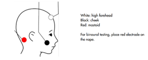
- Patients should lie on their back in a quiet room. It is best to perform the exam on a sleeping patient, but it is possible to perform with patients who are awake. With children and non-cooperating patients, it is possible to use sedation or complete anaesthesia. Parts of the skin are pre-chosen for electrode placement, the skin is treated with abrasive paste and wiped with alcohol solution. On this part of the skin we stick the electrodes. Usually in clinical practice we use 4 electrodes:
- Red – right processus mastoideus or earlobe (reference electrode)
- Blue – left processus mastoideus or earlobe (reference electrode)
- White- Vertex or upper part of the forehead (active electrode)
- Black – on the cheek or lower part of the forehead (earthing electrode)
Then it is necessary to check whether the impedances of the electrodes exceeds the given value on the machine (usually 5kΩ), if the electrode impedance exceeds this value, we must repeat the procedure. Hearing aids (headphones) are placed on both ears (or are attached to the earcanal in the event of earphones – inside the ear) Then we set the parameters of the examination:
- 1. Type of stimuli
- a. Frequency nonspecific
- (click – broadband sound similar to a short knock; chirp – very short stimuli with a gradually higher frequency – starting with lower pitch tones registered in the apical turn of cochlea, then higher pitch tones registered towards the basal turn of the cochlea → we achieve full cochlear stimulation in one instance and the detected evoked potential is stronger)
- b. Frequency specific
- a. Frequency nonspecific
(different tones, short sounds with a chosen frequency band; narrow-band chirp stimulus similar to chirp but with a smaller frequency band)
- 2. Masking of contralateral ear
- -into one of the ears we send a frequency with a non-specific hum/noise, to prevent not hearing the stimulus sound properly, which would alter the results
- 3. The units of the Intensity of the stimulus are dB
- 4. Repeated frequencies – usually 20 Hz for neurological exams, with higher Hz the speed of the examination increases, but the character of the curves changes
- 5. Numbers of stimuli (averages) – for neurological exams we use a minimum of 2000 stimuli
It is necessary to input the gender and age of the patient because for different groups of patients there are different normative values of latency for each wave. Then the measuring is commenced, and the curve is slowly drawn. For neurological exams the measurements are repeated for different intensities of stimuli. For determining the hearing boundary, the intensity of the stimulus is slowly lowered until the last wave V disappears. The last intensity during which the wave V is visible determines the hearing boundary of the patient.
Record of the exam
- The amplitudes of the AEP are in a range of hundreds of nanovolts. The electric activity of the brain is in a range of tens of microvolts. The AEP are therefore hidden in the electric activity of the brain - if only the evoked potential of one stimulus was recorded, no AEP would be detected. If we average several curves obtained from several stimuli (thousands), we get a resultant curve, which cancels out the electric activity of the brain and gives the AEP.
Evaluation of the exam
- After the termination of the measurements, the doctor must manually mark the waves or check their position if they were marked automatically. Changes in the latency of wave between peak intervals or a visible deformity of waves may be a sign of a pathological state. When searching for the hearing boundary, we choose the last curve on which we see wave V, the intensity of the stimulus of this wave is the default value for the estimate of the hearing boundary.
PRACTICAL Portion:[edit | edit source]
- Task 1. - Perform the BERA (Brainstem Evoked Response Audiometry) test on the right ear at different intensity levels and evaluate.
- Task 2. - Test the hearing threshold of the right ear using lower frequency stimuli.
Equipment:
- Sentiero Advanced Diagnostic ABR
- 3 Electrodes
- Headphones
- Abrasive paste
- Alcohol
Task 1:
Please handle the earphones carefully. In case of emergency, pull the cords out of the system output socket. If the system malfunctions notify the head professor immediately.
1. Prepare the Patient[edit | edit source]
- 1.1.) Patient lies down on a table. If that is not possible, sit the patient comfortably in a chair. The patient‘s head should be supported.
- 1.2.) Clean the areas of application with the abrasive paste (peeling cream) and wipe with ethanol.
- 1.3.) Place the electrodes onto the areas of application, apply conductive paste to the skin before attaching the electrodes.
- 1.4.) Put the earphones onto the patient, RED on the right ear, and BLUE on the left ear.
2. Device Preparation[edit | edit source]
- 2.1.) Plug the electrode and earphone cords into the device “SentieroAdvanced.” Headphones into the Blue socket and the Electrodes to the White socket.
- 2.2.) Turn on the device using the button on the right hand side of the device.
3. Create a new patient file as follows:[edit | edit source]
- 3.1.) Press the green button with the patient symbol
- 3.2.) Press the green button with the + symbol
- 3.3.) Fill out the ID, name, and date of birth - number and letter of your groups and team, followed by a number of the student in the team in the alphabetical order - eg. 4J2
- 3.4.) Return to the previous screen
4. Test Settings[edit | edit source]
- 4.1.) Select the test ABR, and then select CHIRP35
- 4.2.) Select the Tools symbol
5. Select the following settings:[edit | edit source]
- 5.1.) stimulus - chirp
- 5.2.) Stimulus Polarity - alternating
- 5.3.) Camoflauge Noise - Yes
- 5.4.) (down button)
- 5.5.) Intensity - leftmost column 70, 50 and 30 dB
- 5.6.) (down button)
- 5.7.) Frequency of the stimulus - 20 Hz
- 5.8.) Averages - 2000
- 5.9.) (button down)
- 5.10.) No changes to the parameters on this page.
- 5.11.) (button down)
- 5.12.) (stop criteria - 10 nV, minimal wave amplitude 5-20 nV)
- 5.13.) (button down)
- 5.14.) Age Category - Adult
6. Click the OK button and return to the previous screen for selecting the ear that is to be tested.[edit | edit source]
7. Select the right ear.[edit | edit source]
8. The device will check the electrode impedance.[edit | edit source]
If any one of the electrodes has an impedance higher than 6 kΩ, you should re-attach the electrode (steps 1.2 and 1.3, using the conductive paste). If the impedance of any of the electrodes is higher than 12 kΩ, then the device should not allow the test to be performed. You must re-apply the t electrodes.
9. Click the red play button to start the test.[edit | edit source]
10. The device will complete the test according to the parameters.[edit | edit source]
It is necessary for the acoustic and electromagnetic disturbance around the test area to be at a minimum (maintain quiet and turn off all mobile phones). The patient needs to remain still and undisturbed as these factors may affect the data.
11. Evaluation of the Test[edit | edit source]
- 11.1.) After the test, the results will show up on the screen. Swipe left to go to the next screen containing waves. Mark the waves (wave I around 1-2ms, wave III around 3-4ms, wave V around 5,5-6ms).
- 11.2.) After marking all the waves, move to the third screen which displays the latency of individual waves and the curve intensities, from which the waves originate. Coloured areas mark normal values.
- 11.3.) Move to the fourth screen, where the data for latency and interpeak values is compiled. Insert this data into the Excel protocol data sheet on the computer. The data sheet MUST be opened with Microsoft Excel (as programs such as Open Office Excel will not create the correct graphs).
- 11.4.) Evaluate the latency from the graphs and formulate a conclusion.
Task 2[edit | edit source]
(It is not possible to carry out this task at the moment but will be included in future practicals)
1. The second task is a continuation of the first task, so please do not unhook the patient from the device.
2. Using the back button return to the original screen.
3. We will repeat the protocol starting from Step 3 in the previous test, but with different parameters.
- 3.1.) Stimulus - low-(chirp)
- 3.2.) Stimulus Polarity - alternating
- 3.3.) Camoflauge Noise - yes
- 3.4.) (button down)
- 3.5.) Intensity - leftmost column 50, 40, 30, 20, 10 dB
- 3.6.) (button down)
- 3.7.) Frequency of Stimulus - 39 Hz
- 3.8.) Averages - 4000
- 3.9.) (button down)
- 3.10.) No changes to the parameters on this page.
- 3.11.) (Stopping criteria - 10 nV, minimal wave amplitude 5-20 nV)
- 3.12.) (button down)
- 3.13.) Age Category - Adult
4. The process of the examination is the same as Step 4 of Task 1
5. Evaluation of the Test
- 5.1.) Only wave 5 is important in the evaluation of this test. Use the same procedure as in the previous task to mark the curve of wave 5. Proceed from the curve of the strongest stimulus to the curve of the weakest stimulus intensity. The intensity of the stimulus of the first curve, on which we are not able to safely mark wave 5, is the initial value of the intensity for estimating the auditory threshold.
- 5.2.) It has been empirically found that humans hear acoustic stimuli with an intensity lower than the intensity of the stimulus of the last curve, on which wave 5 was marked. Therefore, the so-called correction factor, which depends on the stimulus frequency, must be deduced from the default threshold estimate.
| Stimulus Frequency | 500 Hz | 1000 Hz | 2000 Hz | 4000 Hz |
|
|
|
|
|
1. Because of the stimulation of about 500 Hz in the ear, we use a correction factor of -20 dB (For example, we have identified the last wave V on a 30 dB stimulus curve, so for the sounds at frequencies close to 500 Hz the estimated value of the hearing threshold around is 10 dB).
2. Insert the results of the test into the Excel protocol data sheet and then write a conclusion.
References:[edit | edit source]
How-To-ManualSenti&Sentiero,
. dokumentu 100893-EN ze dne 8. 9. 2017, PATH MedicalGmbH, found at: https://pathme.de/wp-content/uploads/pdf/epubli_printversion0802_MA_SentiSentiero_How-To-Manual_EN_05.pdf
SentieroAdvanced ABR DiagnosticQuick Start Guide, ze dne 12. 1. 2017, PATH MedicalGmbH, found at: https://pathme.de/wp-content/uploads/quickguides/100800-17_Sentiero-Advanced-ABR-diagnostic-Quick-Start-Guide.pdf
Návod k použití – Eclipse CS, ze dne 1. 5. 2015, Interacoustics A/S, found at: https://www.interacoustics.com/support/eclipse/eclipse-manuals/331-instructions-for-use-eclipse-cs/file
M. (2015, April 20). Online Help [PDF]. Germering: PATH medical GmbH.
Online Help, found at: https://www.docdroid.net/S8akOjT/mira.pdf
DRŠATA, Jakub a Radan HAVLÍK, Viktor CHROBOK, ed. Foniatrie - sluch. Havlíčkův Brod: Tobiáš, 2015. Medicína hlavy a krku. ISBN 9788073111595.
KABÁTOVÁ, Zuzana a Milan PROFANT. Audiológia. Praha: Bratislava, 2012. ISBN 9788024741734.
STEJSKAL, Lubor. Evokované odpovědi a jejich klinické využití. Praha: Praha Publishing, 1993.


