Electrodes for diagnostics
TOO TECHNICAL, YOU CHOSE A REFERENCE FOR PHYSICISTS & ENGNEERS NOT FOR MEDICAL DOCTORS. I HAVE MY DOUBTS WHETHER YOU UNDERSTOOD WHAT YOU HAVE WRITTEN.
Introduction[edit | edit source]
An electrode is a conductor that passes an electrical current from one medium to another, usually from an ENERGY source to a device or material. Modern medicine applies various BIOPOTENTIAL MEASURING techniques such as electrocardiography, electromyography and electroencephalography to name but a few. However, this essay only deals with electrodes for biomedical measurements in due consideration of the EEG.
Technical design and types of EEG electrodes[edit | edit source]
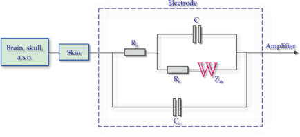
The electric characteristics of electrodes are generally nonlinear and a function of the current density at their surface. Thus, having the devices represented by linear models, needs that they can be operated at low potentials and currents. Electrodes can be represented by an equivalent circuit, (shown below) in which and represent the impedance associated with the electrode-electrolyte interface and polarization. is the series resistance associated with interfacial effects and the resistance of the electrode materials themselves. is the maximum, a few hundred ohms large, ohmic resistance of the electrode gel and resistance ohmic component of the electrochemical process during the derivative signal, denote the Warburg impedance (Figure 1).
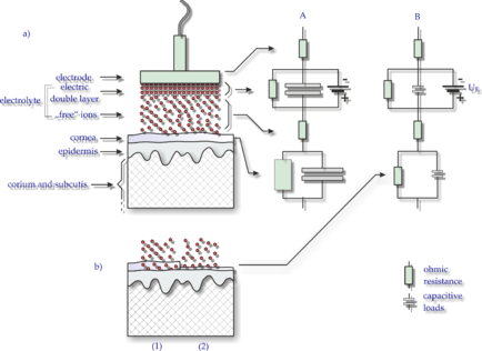
Figure 2 shows the decisive for the electrode contact resistance components at the interface electrode/scalp and their representation in the form of electrical equivalent circuit diagrams. (A) The size of the values for the ohmic and capacitive resistors symbolizing their influence on the contact resistance (and not their electrical properties!). The second (B) electrical equivalent circuit diagram represents low electrode impedance of non-polarizable electrode. denotes the electrode potential.
Two examples for different types of electrodes[edit | edit source]
For the transport of the electrical neuronal signals to the writing system of the EEG device, free electrons are the charge carriers. However, the charge transfer is mediated by ions in the tissue and in the transmission of the scalp to the electrode. For EEG leads of the tissue and below the electrode the most important electrical charge carriers are chloride- and sodium ions. Solvents that are broken down into such ions and can thus transport the electric charges are called electrolytes.
Polarizable electrode[edit | edit source]
An electrode characterized by an absence of net current between the two sides of the electrical double layer.
Non polarizable electrode[edit | edit source]
An electrode whose potential is not affected by the current passing through it.
Signaltransmission to the EEG[edit | edit source]
Once the bioelectric current is transduced at the surface of the electrode, the electric current travels along the path of least resistance to the EEG amplifier. In most cases, this transmission of the EEG signal occurs along conductive wiring leading from sensing electrodes to the circuitry of the amplifier. Lead wiring is typically con-structed of a highly conductive material and is typically both insulated and shield-ed. Insulation of lead wires typically takes the form of a protective jacket surround-ing the wire, which has very high resistance to the flow of electric charge, simply preventing the transmission of charge in one lead wire from influencing the signal in neighboring leads. The shielding of lead wires reduces the extent to which elec-trical noise in the environment interferes with the transmission of the EEG signal. The importance of protecting lead wires from electrical noise cannot be underestimated, because virtually all of the electrical noise in EEG recordings is introduced in the lead wires between the electrodes and the amplifier.
Outlook[edit | edit source]
Understanding the electrochemical interaction in electrodes helps to clarify their behavioral nuances. It enables designers to understand the challenges clinicians face when placing electrodes on patients. A thorough understanding of the elec-trode to skin interface ensures that the signal acquisition is correct and reliable, en-abling the clinician to correctly diagnose the patient’s condition.
Links[edit | edit source]
http://web.mnstate.edu/marasing/CHEM480/Handouts/Chapters/Electrodes%20and%20Potetiometry.pdf http://www.groupes.polymtl.ca/gbm8320/Ch8_P1_Electrodes_web.pdf
Related Articles[edit | edit source]
http://www.fis.uc.pt/data/20062007/apontamentos/apnt_134_5.pdf
http://www.braincoretherapy.com/wp-content/uploads/2014/01/Neurophysiologic-Basis-of-EEG.pdf
Bibliography[edit | edit source]
S. Zschocke. H.-C. Hansen (Hrsg.), Klinische Elektroenzephalographie, DOI 10.1007/978-3-642-19943-1_1, Springer-Verlag Berlin Heidelverg 2012
Dieterich M, Brandt T (1989) Elektronystagmographie: Methodik und klinische Bedutung. EEG-Labor 11: 13-30wikile


