Differential amplifier 2

One of the most important components of the chain for sensing the bioelectrical signal is the input differential (differential, difference) amplifier. The principle of the differential amplifier is an amplification stage with a symmetrical input, which has significant advantages for biosignal processing.
In principle, the input consists of an inverting and a non-inverting input - both related to ground potential - "ground terminal" 1). The useful biosignal is sensed along with the interference by this pair of inverting and non-inverting inputs. The task of the differential stage (amplifier, preamplifier) is to amplify the differential signal - i.e. the useful signal, while suppressing the in-phase signal (agreeable, of the same polarity, which is usually caused by interference of various kinds) as much as possible . From an electrical point of view, the earth electrode connected "in the middle" is of fundamental importance in practical use (see 1)) and is connected to a suitable place in order to eliminate unwanted interference as much as possible (e.g. unwanted action potentials or artifacts caused by electrical stimulation). An example is the placement of an earth electrode on the wrist during evoked EMG , if the signal is taken from the fingers or palm and the EMG is stimulated by an electrode placed in the forearm area. Or in ABR recording , when the ground electrode is placed on the face (on the neck) to eliminate the myographic signal of the neck muscles.
- Examples of connecting a differential amplifier stage
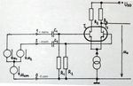
Differential amplifier with a pair (twin) of J-FET transistors
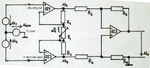
Differential amplifier with operational amplifiers (usually with unipolar elements at the input)
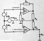
Other connections with operational amplifiers


Properties of the differential amplifier that fundamentally affect the quality of the sensed signal[edit | edit source]
- input impedance
- common mode rejection ratio (CMRR - Common Mode Rejection Ratio)
- supply voltage rejection factor (SVRR - Supply Voltage Rejection Ratio)
- noise characteristic
- linear phase characteristic
- constant gain in the desired band
Input impedance - in order to use as little as possible the transition impedance of the used electrodes (impedance between the electrode and the skin), it is necessary for the differential amplifier to have the highest possible input impedance (on the order of tens to hundreds of MΩ)
Co-phase signal suppression factor − in the event that the input signal is disturbed by some external influence (electric field induced by drive units - power motors, sterilizers, lighting, mobile phones, MRI , contact potential of applied electrodes), it is necessary that the voltage arriving at both differential amplifier inputs in the same phase, was suppressed as effectively as possible. A typical CMRR value ranges from at least 80 dB above (ie, the input interfering signal will be attenuated by 10,000x more).
Supply voltage change suppression factor − although very well stabilized power supplies are used in modern devices to supply input circuits, it is necessary to eliminate the influence of supply voltage changes and interference coming from this direction. To limit interference from the network, network interference filters are also included in the network parts of imaging medical devices.
Noise characteristic - the inherent noise of the amplification stage is multiplied in each subsequent amplification stage of the bioelectric signal processing chain together with the useful signal, therefore the noise characteristics of the input differential amplifier are its key feature. They are given in units of μV relative to the input (ie, if the noise amplitude at the output of the bioelectric signal amplifier is 1 mV and the amplifier has a gain of 40 dB, the inherent noise of the amplifier relative to the input is 1000x smaller, ie 1 μV). The noise characteristics of the amplifier are particularly negative for low-amplitude signals, e.g. fetal ECG, ABR (acoustically evoked brainstem responses), EEG, ERG (electroretinograph), etc. The influence of not quite optimal noise properties of the differential input amplifier, or the entire chain for processing cyclic signals can be removed to some extent by special techniques, e.g. so-called averaging (typically when recording evoked potentials).
The linear phase characteristic - is important so that the shape of the recorded curve is not distorted (the spectrum of a periodic ECG signal, EEG, etc.) consists of a fundamental frequency that corresponds to the period of the signal and a number of harmonic components that have a frequency in whole multiples of the fundamental frequency (see Harmonická analýza). If the harmonic components of the signal were amplified with a different phase than the fundamental harmonic, the shape of the signal would fundamentally change.
Constant amplification in the desired band − each type of bioelectrical signal has its own frequency range in which it is usually sensed and evaluated. From above it is limited by a filter of the type DP - low pass, in medical practice called a "filter", from below it is limited by a filter of the type HP - high pass, in medical practice called "time constant". Again - in order not to change the shape of the amplified signal, as mentioned earlier with the phase characteristic, it is necessary that the gain is constant - the same for all frequency components of the signal.
Sources[edit | edit source]
- HENYCH, D. Elektromyografický zesilovač. Prague : ČVUT - Faculty of Electrical Engineering, 1988, diploma thesis